************* Section 4 excerpt *********
RF-601A PRINCIPLES OF OPERATION RF COMMUNICATIONS
HARRIS RF
COMMUNICATIONS
RF-601A GENERAL INFORMATION
SECTION 1
GENERAL INFORMATION
1.1 SCOPE
This technical manual describes and contains the necessary information to install, operate, repair and maintain the RF-601A Antenna Coupler Group. Hereinafter, the RF-601A Antenna Coupler Group will be referred to as the RF-601A.
NOTE
References in this manual are made with respect to a pnmary power source of 115 Vac Some units are supplied with a 115/230Vac primary power transformer (Part no. 0902-6135). See RF-601A/C schematic diagram located in section 5 of this manual for 230 Vac strapping. When used with the RF-130 and AN/URT-23 transmitting systems, the RF-601A derives its power from the transmitter, which is normally 115 Vac regardless of primary power. The RF-601A should, therefore. be strapped for 115 Vac.
1.2 DESCRIPTION
1.2.1 General
The RF-601A (shown on the front page) is an automatic antenna tuning system intended primarily for surface ship and shore use with radio transmitting sets RF-350 (when used with an RF-353), RF-270-05A, RF-130-01 Series, RF-1130-0 1 Series, and RF-1550R. However, the equipment design includes provisions for manual and semi-automatic tuning, thus making the system readily adaptable for use with other radio transmitters with up to 1 kW power output. In addition, the manual tuning capability is useful when a failure occurs in the automatic tuning circuitry. Also, tuning can be accomplished without the use of RF power (silent tuning). This method is useful in installations where radio silence must be maintained except for brief transmission periods. The RF-601A consists of an antenna coupler (normally mounted at the base of the antenna) and an antenna coupler control unit (normally mounted with the associated radio transmitter).
1.1.2 RF-601A/CU Antenna Coupler
The function of the RF-601A/CU is to match the impedance of a 15, 25, 28, or 35 foot (4.57, 7. 62, 8. 53, or 10.67 m) whip antenna to a 50-ohm transmission line, at any frequency in the 2.0 to 30.0 MHz range. When operating in a compatible radio transmitting system, control signals from the associated antenna coupler control unit automatically tune the RF-601A/CU matching network in less than five seconds. During manual and silent operation, tuning is accomplished by the operator with the controls mounted on the antenna coupler control unit. A low power (not to exceed 200 watts) CW signal is required for tuning. Once tuned, the RF-601A/CU is capable of handling 1 kW of PEP and average power.
The RF-601A/CU is enclosed in an aluminum, air-tight, pressurized case that approximately 29. 5 inches long, 15 inches wide, and 10.5 inches high (75.5 x 38.5 x 27.0 cm). Access is gained to the chassis by removing the dome-shaped cover from the case. Fins on the bottom of the case carry heat from the unit. Six mounting feet enable the unit to be attached to the mast of a ship at the base of a whip antenna. The RF-601A/CU is pressurized to 6 psig (0.42 kg/cm2) with dry nitrogen to aid internal heat transfer and prevent corona and arcing. All components of the RF-601A/CU are secured to a chassis which is mounted to the case so that an air duct exists between the chassis plate and the case. An internal fan circulates the nitrogen operand through the heat producing elements and then through the air duct. While passsing through the air duct, the nitrogen loses its heat to the bottom of the case. This heat is then transferred to the ambient by convection through the fins on the case and by conduction through the mounting feet.
1.2.3 RF-601A/C ANTENNA COUPLER CONTROL
The function of the RF-601A/C is to provide the power and control signals required to tune the RF-601A/CU. The control signals are either automatically produced by the RF-601A/C when a tune cycle is initiated, or manually produced with the front panel controls. All DC operating voltages are produced from a 115 volt, 49 to 63 or 350 to 450 Hz, single phase primary power source. Metering and protection circuits are provided to enable complete control of the RF-601A/CU from the remotely positioned RF-601A/C.
The circuits of the RF-601A/C are all mounted on a chassis and panel assembly housed in an aluminum case approximately 5 inches high, 19 inches wide, and 8.5 inches deep (12.7 x 48.3 x 21.6 cm). The chassis and panel assembly is attached to the case with a hinge and secured by four front panel captive screws. Connections between chassis and connectors on the rear of the case are made through a flexible harness assembly and filter box.
1.3 REFERENCE DATA
The following data is the electrical characteristics of the RF-601A.
| a. | Frequency range: 2.0 to 30.0 MHz |
| b. | RF signal capability: LSB, 156, USB, CW, FSK and Compatible AM. |
| c. | RF power capability: 1000 watts average and PEP. |
| d. | Primary power requirements: 115 volts, 48 to 63 or 350 to 450 Hz, single-phase. Units with 2A1T1 may use a 230Vac, 48 to 63 or 350 to 456 Hz, single phase primary power source. |
| e. | VSWR: 1.5:1 maximum when tuned. |
| f. | Antenna types: 15, 15, 28, or 35 foot whip (4.57, 7.62, 6.53, or 10.67 m); 35 foot (10.67 m) preferred. |
| g. | Tuning time: Less than 5 seconds in automatic operation. |
| h. | Modes of operation: Manual,Silent,Automatic |
| i. | Temperature limitations: -28 to + 65§C for RF-601A/CU; 0 to +50C for RF-601A/C.. |
| j. | Power consumption: 80 watts maximum (continuous); 130 watts maximum (intermittent for less than 5 seconds). |
| k. | Input impedance: 50 ohms unbalanced when tuned |
| l. | The diode and transistor complements are shown in tables 1-I and 1-2, respectively |
************* Section 2 excerpt *********
RF-601A INSTALLATlON RF COMMUNICATIONS
NOTE
References in this manual are made with respect to a primary power source of 115 Vac. Some units are supplied with a 115/230 Vac primary power transformer (part number 902-6135). See RF-601A/C schematic diagram located in section 5 of this manual for 230 Vac strapping. When wed with the RF-130 and AN/URT-23 transmitting systems, the RF-601A derives its power from the transmitter which is normally 115 Vac regardless of primary power. The RF-601A should therefore be strapped for 115Vac.
2.3 SITE SELECTION
In selecting a shipboard installation site, adequate consideration must be given to space requirements (figure 2-1). When the RF-601A/C is installed with the above mentioned transmitters, the space requirements for the system will satisfy the needs of the RF-601A/C. When the RF-601A/C is hard-mounted adjacent to the associated radio transmitter, space should be provided to allow the hinged front oanel to be opened for servicing and for cable bends and cable removal at the rear of the unit. The antenna should be mounted as high above the ship`s superstructure as possible. The RF-601A/C must be mounted as close to the antenna base as possible to allow interconnection with a heavy copper conductor not to exceed18 inches (45.7cm); 12 inches (30.5 cm) or less is desired. Mount the RF-601A/CU in a vertical position with its antenna insulator upward. The interconnectinq cable between the RF-601A/CU and RF-601A/C should not exceed 500 feet (152.4 m). In selecting a shore installation site, similar considerastions must be given to space requirements and cable lengths.
The antenna should be mounted high enough to clear any surrounding hills, woods, or buildings. In addition, the antenna should be located as far as possible from any high power transmission lines, to prevent interference.
NOTE
When the RF-601A Antenna Coupler is installed in a sea spray or water corrosion environment, apply Dow Corning DC-5 compound to the coupler insulator. Clean the insulator terminal with hot water and dry with a lint-free cloth before applying the DC-5. Apply a 1/8 inch thick coating of DC-5 over the insulator and ground connections.
The coated insulator may leak RF current to ground when wetted by sea spray,squalls, or rainy weather, but the leakage will stop when the water path is broken. If the insulators are not coated, they will degrade slowly, from moist salt accumulation to the point of arcing and/or shorting.
************* Section 4 excerpt *********
RF-601A PRINCIPLES OF OPERATION RF COMMUNICATIONS
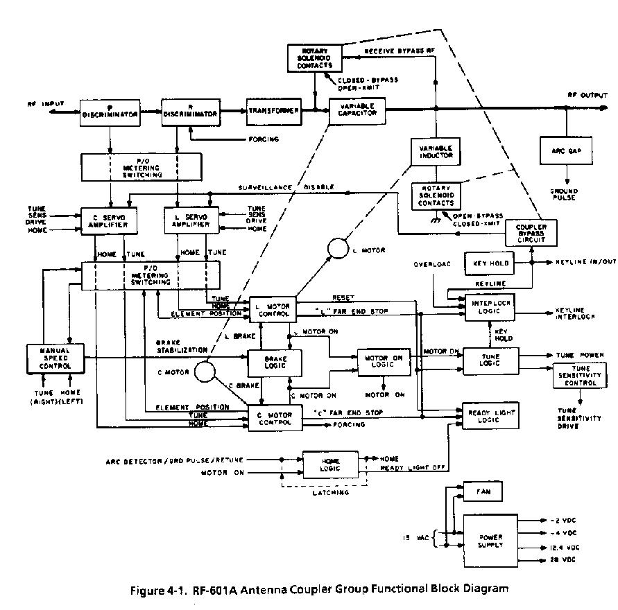
applied to the servo amplifiers turn on their respective home output stages, grounding the home output lines. The home lines are connected directly to the motor control circuits (paragraph 4.2.5) With the home input lines grounded, the two motor control circuits apply a ground to one side and 28 Vdc to the other side of their respective servo motors with a polarity that drives the tuning elements to home. The grounds are also applied as L MOTOR-ONand C MOTOR-ON signals to both the brake logic and the motor-on logic. This produces a positive MOTOR-ON OUTPUT signal from the motor-on 1ogic which is applied to the home logic to lock that circuit on until the tuning elements reach home. The motor on grounds energize the brake logic to release the motor brakes.
As each tuning element reaches home (maximum C, minimum L), its home end stop switch breaks the ground connection to its servo motor. Thus, the MOTOR-ON signal for that element is removed from the brake and motor-on logic circuits. The brake logic for the respective motor de-energizes, engaging the brake for that motor. Also, when the variable capacitor reaches home, its end stop switch supplies a FORCING GROUND signal to the R discriminator (as described below). When the variable inductor reaches home, its end stop switch supplies a reset (ground) signal to the tune and ready light logic. This RESET GROUND is applied through the tune logic to the transmitter as the tune power signal. The RESET GROUND also sets the sensitivity of the servo amplifiers to maximum as required for low power (50 to 250 watt) tuning. The cycle halts at this point and remains in the conditions mentioned above until the system is keyed.
Momentarily keying the system releases the key interlock (after a slight time
delay by the interlock logic), allowing the system to assume a keyed condition.
Since the TUNE POWER signal is being applied to the transmitter, a low level (
I50 watt) output from the transmitter is applied to the RF-601A/CU . The B
discriminator samples RF line voltage and current to produce a dc error signal
proportional to the deviation of the line reactance from 0 ohms. The R
discriminator samptes RF line voltage and current to produce a DC ERROR signal
proportional to the deviation of the line resistance from 50 ohms. These error
signals are applied through the metering and switching circuit to
the servo amplifiers. The servo amplifiers will turn on, grounding the tune
output lines to their respective motor control circuits. With the tune input
lines grounded, the motor control circuits apply a ground to one side and 28 Vdc
to the other side of their respective servo motors with a polarity that drives
the tuning elements towards a tune position. The grounds are also applied to the
the brake logic to release the motor brakes. As the tune point is approached, it
is sometimes necessary for the elements to be "jockeyed" back and forth;
the polarity of the discriminator outputs change as required to cause the motors
to be driven in the right direction. For some antenna
impedances at the
lower part of the frequency range, the normal level of the error signals from
the discriminators is not sufficient to turn on the servo amplifiers;
therefore, a forcing-ground is applied to unbalance the R discriminator,
resulting in an error signal of sufficient level to the Lservo
amplifier. This forces the variable inductor to move in a tune direction.
The forcing continues until the impendance changes sufficiently to produce
an output from the 0 discriminator. At this time, the variable capacitor will
move in a tune direction, opening its home end stop switch. This removes the
forcing-ground to the R discrimator, allowing normal tuning to take over.
The individual motor-on grounds applied to the brake logic are also applied to the motor-on logic while tuning, as during the home cycle. Therefore, the motor-on logic produces a positive motor-on output which is applied to the tune logic circuits. This positive level energizes the tune logic to lock in the tune power ground to the transmitter and TUNE SENSITIVITY drive signal to the servo amplifiers, and produces a KE Y HOLD signal to the keying logic. The KEY HOLD signal energizes the keying logic to lock in the system key. (The MOTOR-ON signal is also applied to the home logic, but an internal clamp prevents that circuit from being energized.) When the tuning elements reach their respective tune positions, the servo logic circuits change state to remove the KEY.MOTOR-ON, TUNEPOWER, and TUNE SENSITIVITY DRIVE signal and engage the motor brakes. This removes all inhibits from the ready light logic. Therefore, the READY light is energized, indicating that the tune cycle has been completed. The automatic tuning cycle requires a maximum of 5 seconds to complete. When the system is keyed, full RF power (1 kW) is applied to the RF-601A/CU by the transmitter. As conditions change the antenna impedance, the discriminator produce error signals to fine-adjust the tuninq elements. Therefore, a tuned condition is always maintained. While fine tuning, internal clamps in the logic circuits prevent MOTOR-ON SIGNALS from activating the home and tune logic circuits. If the RF voltage exceeds a safe limit, an arc will develop across the arc gap, producing a ground-pulse output to the home logic to interlock the transmitters keying and initiate a tune cycle.
4.1.3 Manual Tuning Cycle
Manual tuning is accomplished by the operator with the RF-601A/C front panel
controls. The transmitter power output must be reduced to between 50 and 250
watts, and the system must be keyed by the operator. During this mode of
operation, the outputs from the discriminators are switched, one at time, to the
DISCRIMINATOR NULL meter, as determined by the setting of the L-C switch (which
also selects the variable inductor (L) or the variable capacitor (C) for tuning.
The selected tuning element is adjusted by depressing the LEFT or RIGHT push
button as required to provide a null indication on the DISCRIMINATOR NULL meter.
The elements are alternately adjusted until a null indication is obtained on the
DISCRIMINATOR NULL meter for both the L and the C settings of the L-C switch. To
permit more efficient operator control of element positioning, the speed of the
servo motors (which is very rapid during automatic operation) is reduced by
changing the constant dc input of the synchro motor to an
electronically-governed, pulsed dc (paragraph 4.2.8). The servo amplifiers and
most of the logic circuitry are disabled during manual operation. However, the
key interlock circuit is maintained so that if an element is run up against its
far end stop, or if an underpressure or overtemperature condition exists in the
RF-601A/CU, RF power will be removed from the RF-601A/CU, precluding possible
darmage to the equipment.
4.1.4 Silent Tuning Cycle
Initial silent running is accomplished without using RF power. Therefore, the descriminators, DISCRIMINATOR NULL meter, servo amplifiers, and logic circuits are not used at this time. Each tuning element is set to a pre-recorded indcation on the ELEMENT POSITION meter using the LEFT and RIGHT pushbuttons. As with manual tuning,the dc input to the servo motor is pulsed to obtain a slow tuning speed. The elements are positioned, one at a time, as selected with the L-C switch. (The indications of the ELEMENT POSITION meter must have been recorded for each element at each assigned operating frequency during previous automatic or manual operation.) The ELEMENT POSITION meter indications are provided by potentiometers whose wipers are mechanically ganged to the individual tuning elements. As in manual operation, the key interlock circuit is maintained in case a tuning element is run up against its far end stop switch, or if an underpressure or overtemperature condition exists in the RF-601A/CU. When a full power transmission is keyed in the silent mode of operation, the servo amplifiers, motor control circuits, and brake logic are energized to enable the tuning elements to be automatically fine adjusted, as required, to maintain a tuned condition (during this fine adjustment, the dc to the servo motors is full voltage, not pulsed).
4.1.5 Power Supply and Cooling
The power supply in the RF-601A/C
is the source of all dc voltages required for operating the RF-601A. These
voltages are produced from the 115 Vac, 48 to 63 or 350 to 450 Hz single-phase
primally power input. A single input power transformer with two secondaries is
used. One secondary output is half-wave rectified to provide -4 and -2 Vdc, and
the second is bridge rectified, to provide approximately 50 Vdc unfiltered, and
filtered +28 and +12.4 Vdc. ( The unfiltered dc is filtered in the Manual Speed
Control assembly to provide +10 and +20 Vdc operating voltages for that
assembly). Primary power is also applied to the cooling fan in the RF-601A/CU to
circulate the nitrogen atmosphere, when the internal temperature exceed 80
degrees F.
The fan and the RF-601A/CU case form a heat exchanger to transfer eternally
generated heat to the ambient air.
4.2 DETAILED CIIICUIT DESCRIPTIONS
4.2.1 Matching Network
The matching network (figure 4-2) consists of a transformer (T1), a variable inductor (L1), and a variable capacitor(C1). The function of these components is to transform the impedance of a system antenna to an impednace that is 50 ohms resistive.
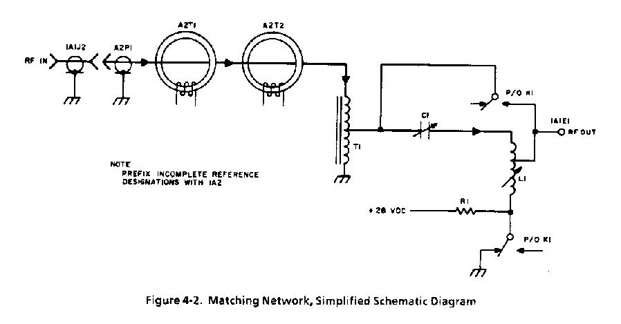
Rotary solenoid K1 is energized (paragraph 4.2.10) if a transmission is not being made, provided the bypass function is switched on. This opens the ground side of inductor Ll and shorts capacitor Cl, thus bypassing the matching network. This allows reception on a frequency different from that of transmission. When the
********************
END OF PAGE